Converting a Tuya Thermostat to ESPHome
I bought a cheap Chinese thermostat to control an infrared heating panel in my office. It ticked all the boxes except one: it's a Tuya device which requires a cloud connection. That's a big no-no for me. So I ripped it apart, soldered some leads onto the PCB and flashed ESPHome onto it. Here's how that went.
But first, some context!
Why an IR panel
The central heating in my office is controlled by a Tado thermostat, but the signal in that room is terrible. It regularly loses connection and stops heating entirely. Not great when you're trying to work in winter.
To stop myself from freezing to death, I bought a supplemental 800W infrared heater. I'd heard good things about IR heating, and after trying it I was immediately sold. It makes you feel warm almost instantly even though the room is still cold.
Only problem: the IR panel only has a basic on/off switch. No thermostat. I looked at Sonoff and Shelly relays, but even with mods, they don't look like a finished product you'd want to put in a wall socket.
TP4W.WHITE
That's how I landed on the TP4W.WHITE: a cheap thermostat that you can plug into a wall socket, looks decent, has a built-in relay, temperature sensor, and a nice LED display.
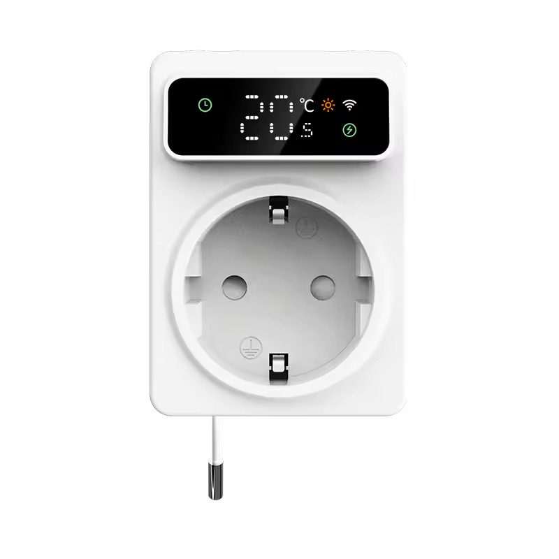
It ticked all the boxes, except one. It's a Tuya device, meaning it can only be controlled through their cloud. I have a strict policy of only buying devices that can be controlled locally via Home Assistant, so Tuya is a no-go[1].
But hope is not lost! I knew some Tuya devices use Espressif microcontrollers, which are fully supported by ESPHome. So I contacted the seller on AliExpress, and after a bit of back and forth, they replied the device is using a BK7231N microcontroller.
I had never heard of that chip before, and feared it might be unsupported. But it turns out it's supported by ESPHome via LibreTiny. So I decided to buy it and see if I could flash ESPHome onto it.
Flashing ESPHome
When the device arrived a few weeks later, I thought it was going to be a simple process. Use tuya-convert to flash ESPHome onto it, add it to Home Assistant, and work comfortably in my heated office.
However, this option requires using a Linux machine, which I didn't have readily available. So instead, I opened up the device to see if it had exposed RX and TX pins to flash ESPHome directly. To my surprise, it did!

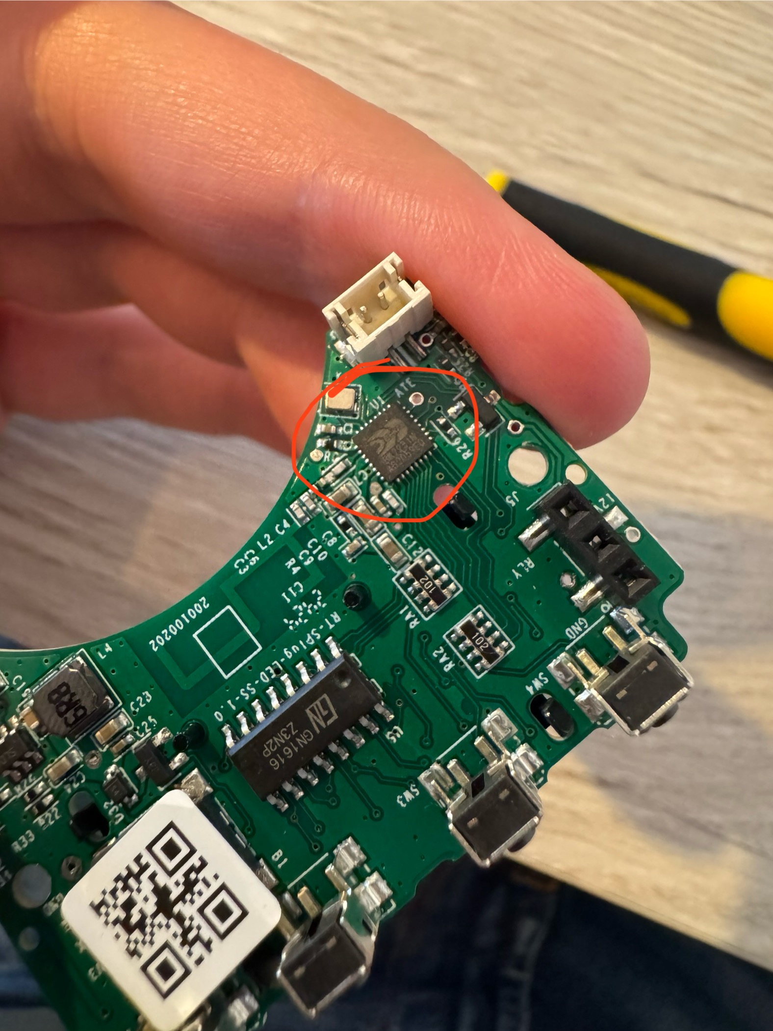 The BK7231N chip.
I soldered some leads to the BK7231N chip's RX and TX pins and connected it to my serial-to-USB adapter. I then dumped the original firmware using bk7231tools and flashed a simple ESPHome firmware onto the device.
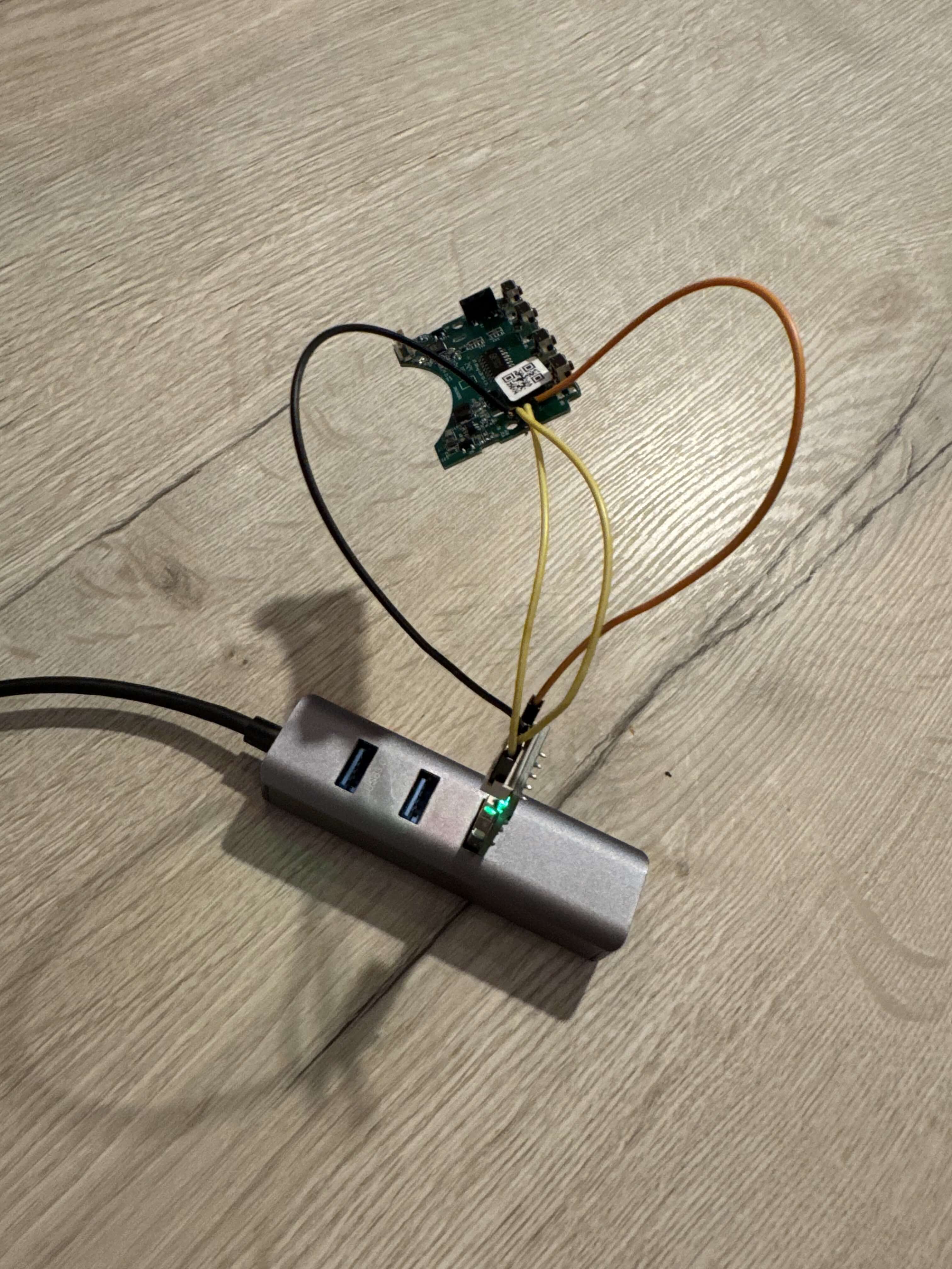
To my surprise, the device booted up and connected to Home Assistant without any issues!
Figuring out the pinout
Next, I needed to figure out how the relay and temperature sensor were connected to the BK7231N.
LibreTiny has a tool to extract a device's pinout from a dumped firmware image and auto-generate an ESPHome config for it. However, for this device that didn't work, and I got this error instead:
The chosen device doesn't contain pin configuration.
Possible causes:
- it has vendor-specific firmware
- it uses TuyaMCU (report error if that's the case!)
Auto-generating ESPHome YAML is not possible.
Well that's a bummer. I would have to figure out the pinout myself.
I mapped all output pins of the chip to input_booleans in Home Assistant. By turning each one on and off, I was able to determine which pin was connected to the relay. But figuring out how the display or thermistor were connected was going to be much harder.
Emailing the manufacturer (it actually worked!)
I decided to try emailing the manufacturer and ask for some help (or more specifically, a pinout). Who knows, maybe they'd take pity on a random European suffering in a cold home office.
AliExpress listed ezAIoT as the manufacturer but in typical AliExpress fashion, that turned out to be a front company reselling someone else's product. I emailed them asking for the pinout but the email bounced immediately.
After reverse image searches, I found the actual manufacturer: RTI-TEK. I sent them an email and to my surprise, they got back to me with the full schematics of the thermostat!
I couldn't believe it. Having the schematics made the rest of this process super simple! In just a short hour, I was able to get almost everything working with ESPHome.
The relay
The easiest part was of course the relay. Setting it up as a GPIO switch was straightforward:
switch:
  - platform: gpio
    id: relay
    name: thermostat_relay
    pin: P22
    internal: true
I marked it as internal because I don't want the raw relay showing up in Home Assistant. Instead, I'll expose a proper thermostat climate entity later.
Temperature sensor (NTC)
The thermostat has a built-in NTC thermistor for measuring room temperature, connected to the ADC on P23 (labeled ADC6 in the BK7231N datasheet).
Getting this to work required chaining three sensors in ESPHome: an ADC reads the raw voltage, a resistance sensor converts that to ohms, and an NTC sensor turns the resistance into a temperature using B-constant calibration:
sensor:
  - platform: ntc
    sensor: resistance_sensor
    name: "Office Temperature"
    id: temperature_sensor
    calibration:
      b_constant: 3380
      reference_temperature: 25°C
      reference_resistance: 10kOhm

  - platform: resistance
    id: resistance_sensor
    sensor: source_sensor
    internal: true
    configuration: DOWNSTREAM
    resistor: 10kOhm

  - platform: adc
    id: source_sensor
    pin: ADC6
    internal: true
    update_interval: 30s
The schematics helpfully included the resistor values and the B-constant. I compared the readings against a calibrated thermometer and they were within 0.5°C. The sensor does heat up slightly after prolonged use, but that's to be expected.
Initially, ESPHome complained about the ADC pin not being an input pin. But that turned out to be an issue with the pin mapping in LibreTiny, something that got fixed quickly when I opened an issue on their GitHub.
Climate entity
With the temperature sensor and relay working, I could create a proper thermostat using ESPHome's built-in thermostat climate platform:
climate:
  - platform: thermostat
    id: climate_thermostat
    name: "Office"
    sensor: temperature_sensor
    visual:
      temperature_step:
        target_temperature: 0.5
        current_temperature: 0.01
    min_heating_off_time: 30s
    min_heating_run_time: 30s
    min_idle_time: 30s
    heat_action:
      - switch.turn_on: relay
    idle_action:
      - switch.turn_off: relay
This gives me a full thermostat entity in Home Assistant where I can set the target temperature in 0.5°C increments. Cheap thermostats often turn on and off rapidly when they reach their target temperature. ESPHome's min_heating_off_time and min_idle_time settings prevent that by enforcing minimum durations between state changes.

The LED display
The thermostat has a segmented LED display showing the current temperature along with several indicators for things like WiFi, heating status, etc.

I don't need the display to work since I mostly control this via Home Assistant, but it would be very nice to have it working.
The display is driven by a GN1616 chip, which appears to be a clone of the TM1638. Lucky for me, ESPHome has built-in support for the TM1638.
The display connects via three pins:
STB (Strobe) -> P16
CLK (Clock)  -> P14
DIO (Data)   -> P28
While ESPHome does support the TM1638, the display on this thermostat uses a non-standard segment layout. Some segments drive icons (WiFi, snowflake, sun) instead of digit segments, so I couldn't just print a number and call it a day.
Through trial and error, I mapped out which bits control which segments and icons:
| Segment | Bit | Icon |
|---|---|---|
| 0 | 0 | ".5" indicator |
| 0 | 1 | Snowflake icon |
| 0 | 2 | Lightning bolt |
| 1 | 0 | Clock icon |
| 1 | 1 | Hourglass icon |
| 1 | 2 | °C indicator |
| 1 | 3 | Exchange icon |
| 1 | 4 | SET indicator |
| 1 | 5 | Sun icon |
| 1 | 6 | WiFi icon |
Armed with this mapping, I wrote an ESPHome display() lambda to bring the display to life. Here's what I wanted it to show:
- WiFi icon: turned on when connected.
- Hourglass icon: turned on while trying to connect to WiFi.
- Sun icon: turned on when the heater is active.
- °C indicator: always shown alongside the temperature.
- ".5" indicator: turned on when the temperature has a half-degree.
One quirk: the display renders characters in reverse order, so I had to account for that when formatting the temperature:
display:
  - platform: tm1638
    id: thermostat_display
    stb_pin: P16
    clk_pin: P14
    dio_pin: P28
    update_interval: 1s
    intensity: 7
    lambda: |-
      static uint8_t segment_0 = 0;
      static uint8_t segment_1 = 0;

      segment_0 = 0;
      segment_1 = 0;

      // WiFi status
      if(id(wifi_connection).is_connected()) {
        segment_1 |= (1 << 6); // WiFi icon
      }else{
        segment_1 |= (1 << 1); // Hourglass icon
      }

      // Relay status
      if(id(relay).state) {
        segment_1 |= (1 << 5); // Sun icon
      }

      float temp = id(temperature_sensor).state;

      if(isnan(temp)) {
        id(thermostat_display).print(" -- ");
      }

      if (!isnan(temp)) {
        segment_1 |= (1 << 2); // °C symbol

        float rounded_temp = round(temp * 2.0) / 2.0;
        int temp_int = (int)rounded_temp;
        bool show_half = (rounded_temp - temp_int) >= 0.5;

        if (temp_int >= 10) {
          int digit1 = (temp_int / 10) % 10;
          int digit2 = temp_int % 10;
          char temp_str[5];
          snprintf(temp_str, sizeof(temp_str), "  %d%d", digit2, digit1);
          id(thermostat_display).print(temp_str);
        } else {
          char temp_str[5];
          snprintf(temp_str, sizeof(temp_str), "  %d", temp_int);
          id(thermostat_display).print(temp_str);
        }

        if (show_half) {
          segment_0 |= (1 << 0);  // .5 indicator
        }
      }

      id(thermostat_display).set_segments(0, segment_0);
      id(thermostat_display).set_segments(1, segment_1);
I'll be honest, low-level code and bit-banging are not my strong suit. Most of this code was generated by AI. But hey, it works!
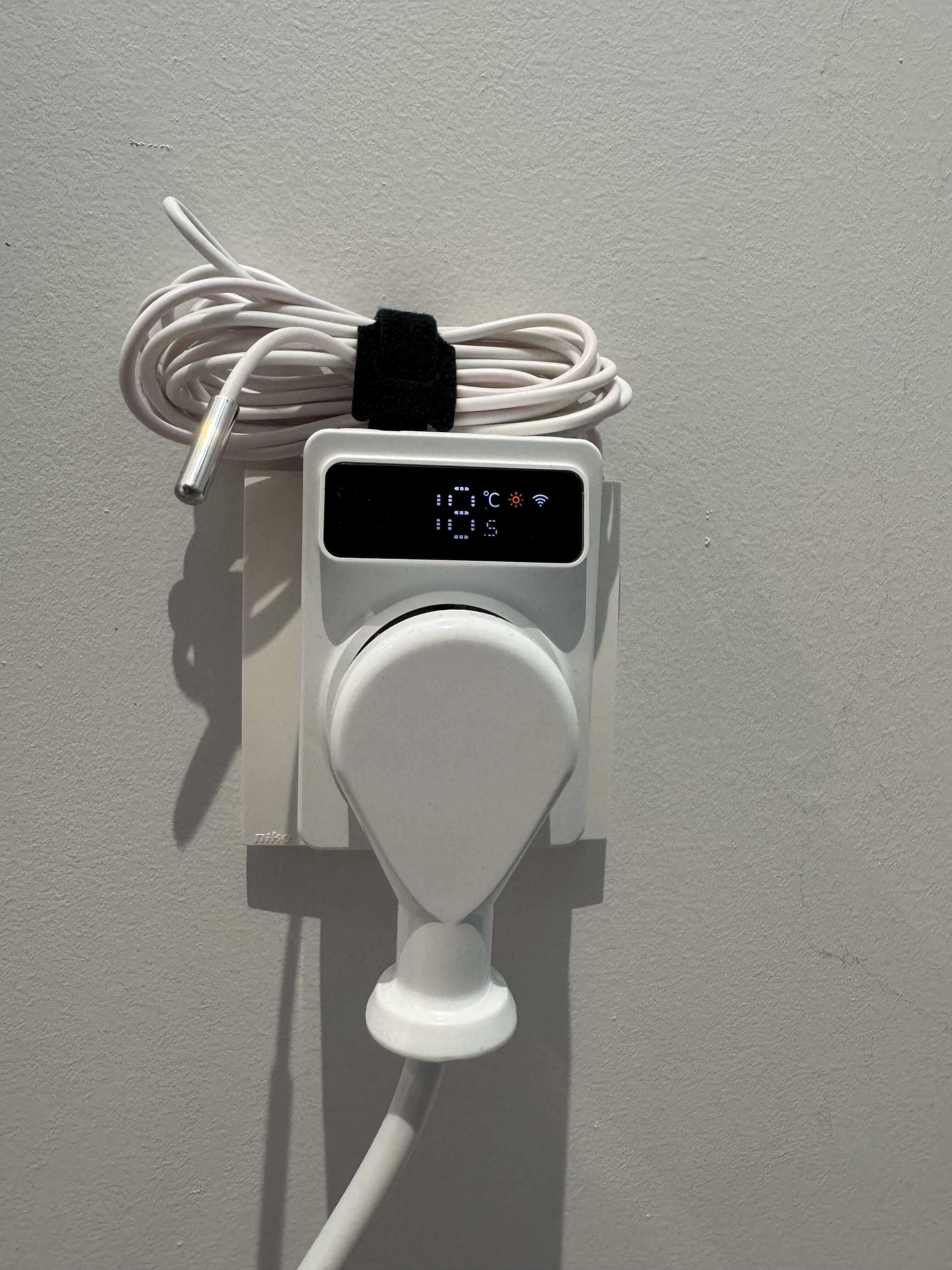 The TP4W.WHITE thermostat running ESPHome while showing the current temperature and state on its integrated display.
Power consumption
I like to keep track of energy usage around the house. While this thermostat doesn't have a power monitoring chip, I can still report power usage accurately by hard coding it because my IR heating panel always uses 800W.
Relay on? Report 800W. Relay off? Report 0W.
sensor:
  - platform: template
    name: "Power"
    unit_of_measurement: "W"
    state_class: measurement
    device_class: power
    lambda: |-
      if (id(relay).state) {
        return 800.0;
      } else {
        return 0.0;
      }
    update_interval: 60s
The buttons
The thermostat has four buttons on top: SET, Plus, Minus, and MODE, but I haven't gotten these working. The schematic shows they're connected to the same GN1616 LED driver, but I couldn't get that to work with ESPHome's TM1638 driver.
I tried a few things, but quickly gave up because I'm not going to use the buttons anyway. This thermostat is tucked away in a corner and mostly controlled via Home Assistant automations.
If you happen to figure out how to get these buttons working, please let me know!
The full ESPHome configuration
Here's the complete config for reference (also check out how I organize my ESPHome configuration files if you're confused by the packages and substitutions):
substitutions:
  devicename: "office-thermostat"
  friendly_name: "Office Thermostat"

packages:
  esphome: !include common/esphome.yaml
  api: !include common/api.yaml
  logger: !include common/logger.yaml
  wifi: !include common/wifi.yaml

external_components:
  - source: ./external_components

bk72xx:
  board: "generic-bk7231n-qfn32-tuya"
  framework:
    version: 0.0.0
    source: https://github.com/Savjee/libretiny.git#master

sensor:
  - platform: wifi_signal
    name: "WiFi Signal Sensor"
    update_interval: 60s
    disabled_by_default: true

  - platform: ntc
    sensor: resistance_sensor
    name: "Office Temperature"
    id: temperature_sensor
    calibration:
      b_constant: 3380
      reference_temperature: 25°C
      reference_resistance: 10kOhm

  - platform: resistance
    id: resistance_sensor
    sensor: source_sensor
    internal: true
    configuration: DOWNSTREAM
    resistor: 10kOhm
    name: Resistance Sensor

  - platform: adc
    id: source_sensor
    pin: ADC6
    internal: true
    unit_of_measurement: "V"
    update_interval: 30s

  - platform: template
    name: "Power"
    unit_of_measurement: "W"
    state_class: measurement
    device_class: power
    lambda: |-
      if (id(relay).state) {
        return 800.0;
      } else {
        return 0.0;
      }
    update_interval: 60s

display:
  - platform: tm1638
    id: thermostat_display
    stb_pin: P16
    clk_pin: P14
    dio_pin: P28
    update_interval: 1s
    intensity: 7
    lambda: |-
      static uint8_t segment_0 = 0;
      static uint8_t segment_1 = 0;

      segment_0 = 0;
      segment_1 = 0;

      if(id(wifi_connection).is_connected()) {
        segment_1 |= (1 << 6);
      }else{
        segment_1 |= (1 << 1);
      }

      if(id(relay).state) {
        segment_1 |= (1 << 5);
      }

      float temp = id(temperature_sensor).state;

      if(isnan(temp)) {
        id(thermostat_display).print(" -- ");
      }

      if (!isnan(temp)) {
        segment_1 |= (1 << 2);

        float rounded_temp = round(temp * 2.0) / 2.0;
        int temp_int = (int)rounded_temp;
        bool show_half = (rounded_temp - temp_int) >= 0.5;

        if (temp_int >= 10) {
          int digit1 = (temp_int / 10) % 10;
          int digit2 = temp_int % 10;
          char temp_str[5];
          snprintf(temp_str, sizeof(temp_str), "  %d%d", digit2, digit1);
          id(thermostat_display).print(temp_str);
        } else {
          char temp_str[5];
          snprintf(temp_str, sizeof(temp_str), "  %d", temp_int);
          id(thermostat_display).print(temp_str);
        }

        if (show_half) {
          segment_0 |= (1 << 0);
        }
      }

      id(thermostat_display).set_segments(0, segment_0);
      id(thermostat_display).set_segments(1, segment_1);

climate:
  - platform: thermostat
    id: climate_thermostat
    name: "Office"
    sensor: temperature_sensor
    visual:
      temperature_step:
        target_temperature: 0.5
        current_temperature: 0.01
    min_heating_off_time: 30s
    min_heating_run_time: 30s
    min_idle_time: 30s
    heat_action:
      - switch.turn_on: relay
    idle_action:
      - switch.turn_off: relay

switch:
  - platform: gpio
    id: relay
    name: thermostat_relay
    pin: P22
    internal: true
Conclusion
I'm super happy with how this project turned out. The thermostat runs great with ESPHome, it's fully functional, seamlessly integrates with Home Assistant and doesn't depend on anyone's cloud.
I'd like to thank the helpful people at RTI-TEK for providing me with their schematics, while also apologizing for taking so long to get around to writing this blog post.
Some Tuya devices can be controlled locally with tools like tuya-local. However, I didn't consider them because they seem like a nightmare to setup, they don't support all devices, and have several limitations ↩︎

